
PROCESS AUTOMATION LAB
List of Major Equipments List of Experiments
1. SCADA tranmission / Distribution System:
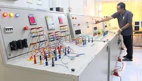
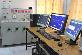
Electrical SCADA Lab in NITC was commissioned in 2008. It was developed by Kalkitech Communications, Bangalore and is one of their first lab setup systems.SCADA lab setup consists of 3 main units.
i. 440/220 kV substation and 220 kV transmissionline model with SCADA
ii. 11 kV Distribution station model with SCADA.
iii. Control centre
The main intention is to give hands on experience for students with systems used for Power System Monitoring, Control, Protection, Automation and Communication.
The main objective is to understand SCADA architecture and communication protocols. It also helps in understanding the working of SCADA system by conducting various experiments on transmission and distribution module to learn the basic operations of SCADA. The typical applications and basic task of scada can be understood, along with its advantages and disadvantages. A brief introduction to unified standard architecture IEC 61850 and MODBUS protocol is also given.
2. PLC
The Programmable Logic Contoller Lab in NITC was commissioned in 2005. Here Programming applications and navigation is done through Allen-Bradley RSLogix 500 software. The basic objective of PLC based experiments is to study of fundamentals of PLC and its architecture. The basic programming concepts can be understood along with establishing communications with the PLC.
2 a. PLC based Lift Control Setup:
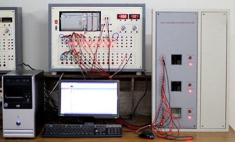
The PLC based Lift Control Setup in the lab is used to control the lift plant model using Allen Bradley PLC with Micrologix 1500 LRP series C. It uses RS232 to establish connection between PC and PLC.
2 b. PLC based Star Delta Starter:
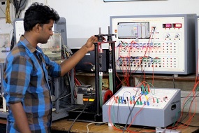
The Star/Delta starter is probably the most commonly used reduced voltage starter. The Star/Delta starter requires a six terminal motor. Here the star to delta transformation is done through PLC ladder program.
2 c. PLC based Batch Process Control Setup:
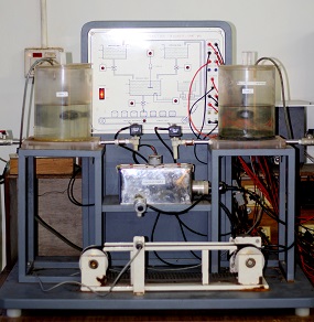
Batch process reactor is a blending process, where two liquids are mixed together to get the output mixture. The programmable logic controller is used to control the whole process. The setup consist of two storage tanks and one process tank along with the blending and heating arrangement. Two pumps are used to maintain the liquid level in two storage tank. The bottle filling arrangement is provided with conveyer belt setup. The whole batch process is controlled by the PLC.
2 d. PLC based servo motor control setup
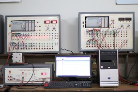
Applying different voltages can control speed of the AC servomotor. For this purpose AC voltage controller has been used. Accordingly triggering angle control for this circuit has accomplished by plc ladder logic program. For measurement of speed an optocoupler is used in conjunction with a square geared wheel connected to the shaft of the motor. The optocoupler measures speed of motor by noting the number of tooth that it encountered in a fixed time. The optocoupler output is given to the analog input port of plc kit. Then control algorithm will compare this value with the default set point value, which give an error signal. This error signal is used in manipulating the firing angle of thyristor circuit to control applied voltage to the servomotor. Ladder logic program also facilitates the user to tune the controller parameters to change the performance of the controller and to set desired speed value.
3. dSPACE DS1104

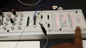
The DS1104 R&D Controller Board upgrades a PC to a development system for rapid control prototyping. The board can be installed in virtually any PC with a free PCI or PCIe slot. Used with Real-Time Interface (RTI), it is fully programmable from the Simulink® block diagram environment and all I/O can be configured graphically. This is a quick and easy way to implement and test new control functions in a real environment.
